
Omnidirectional Polar Pattern | Directional Polar Patterns | Polar Pattern Considerations | Distance Factor | Sound Characteristics | Selecting a Polar Pattern | Line Microphones | Proximity Effect | Feedback
Polar Patterns
In addition to classifying microphones by their generating elements, they can also be identified by their directional properties, that is, how well they pick up sound from various directions. Most microphones can be placed in one of two main groups: omnidirectional and directional.
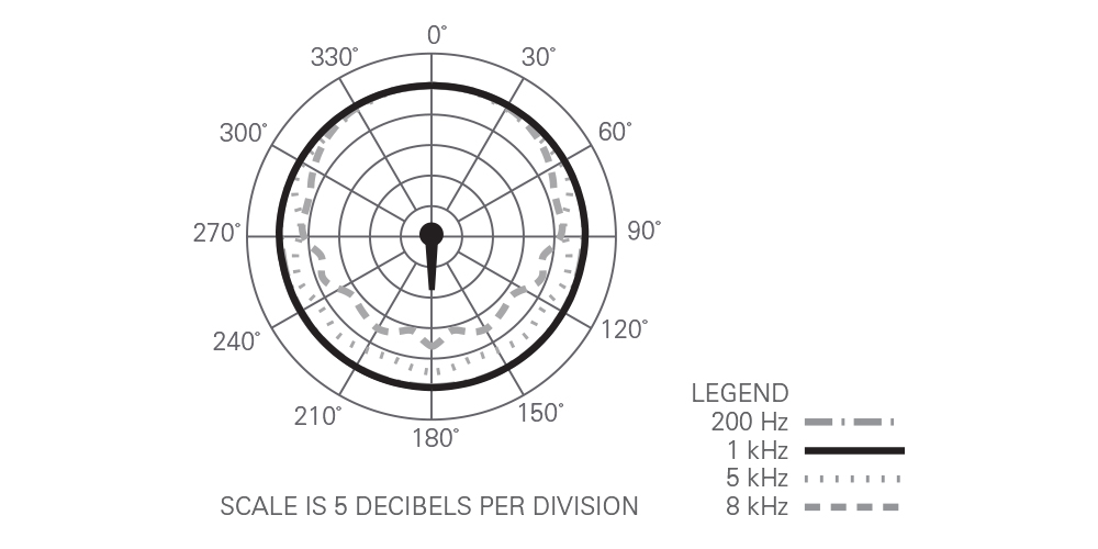
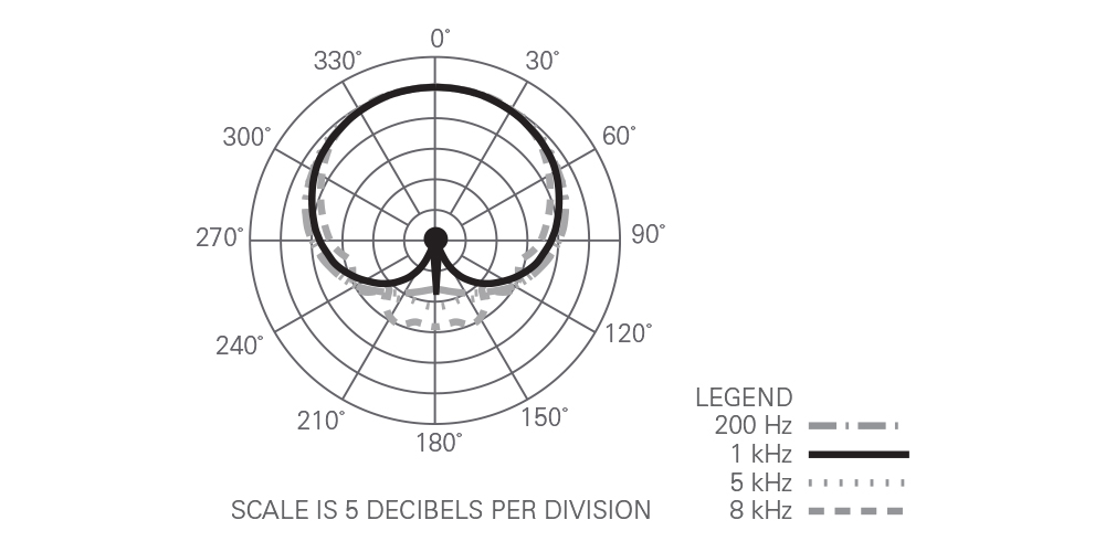
To help you visualize how a directional microphone works, you will find polar patterns in our literature and spec sheets. These round plots show the relative sensitivity of the microphone (in dB) as it rotates in front of a fixed sound source. You can also think of them as a horizontal “slice” through the pickup patterns illustrated in Figures 3 and 4.
Omnidirectional Polar Pattern
Omnidirectional microphones are the simplest to design, build and understand. They also serve as a reference against which each of the others may be compared. Omnidirectional microphones pick up sound from just about every direction equally. They’ll work about as well pointed away from the subject as pointed toward it, if the distances are equal. However, even the best omni models tend to become directional at higher frequencies, so sound arriving from the back may seem a bit “duller” than sound from the front, although apparently equally “loud.”
Figure 3: Omnidirectional Microphone
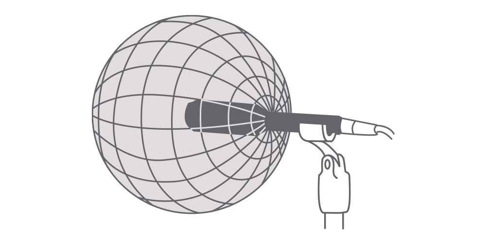
The physical size of the omnidirectional microphone has a direct bearing on how well the microphone maintains its omnidirectional characteristics at very high frequencies. The body of the microphone simply blocks the shorter high-frequency wavelengths that arrive from the rear. The smaller the microphone body diameter, therefore, the closer the microphone can come to being truly omnidirectional.
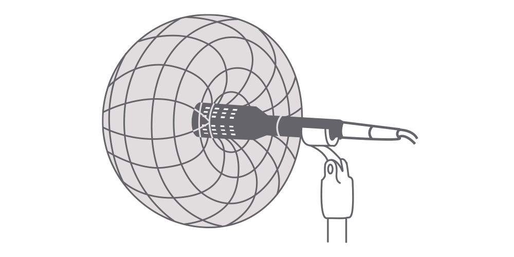
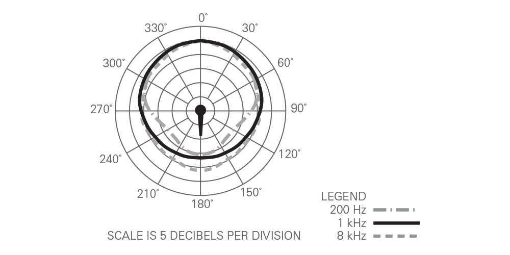
Directional Polar Patterns
Directional microphones are specially designed to respond best to sound from the front (and rear in the case of bidirectionals), while tending to reject sound that arrives from other directions. This effect also varies with frequency, and only the better microphones are able to provide uniform rejection over a wide range of frequencies. This directional ability is usually the result of external openings and internal passages in the microphone that allow sound to reach both sides of the diaphragm in a carefully controlled way. Sound arriving from the front of the microphone will aid diaphragm motion, while sound arriving from the side or rear will cancel diaphragm motion.
The basic directional types include cardioid, subcardioid, hypercardioid and bidirectional. Also included under the general heading of directional microphones is the line – or “shotgun” – microphone, a more complex design that can provide considerably higher directionality than the four basic directional types.
Polar Pattern Considerations
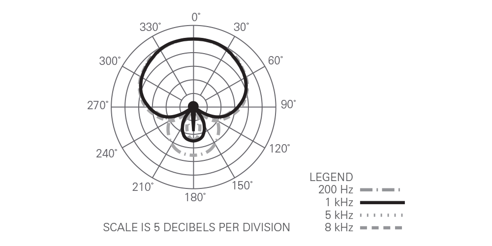
Polar patterns should not be taken literally as a “floor plan” of a microphone’s response. For instance, in the cardioid pattern illustrated, response is down about 6 dB at 90° off-axis. It may not look like much in the pattern, but if two persons were speaking equidistant from the microphone, one directly on-axis and the other at 90°, the person off-axis would sound as if he were twice as far from the microphone as the person at the front. To get equal volume, he would have to move to half the distance from the mic.
A word of caution: these polar patterns are run in an anechoic chamber, which simulates an ideal acoustic environment – one with no walls, ceiling or floor. In the real world, walls and other surfaces will reflect sound quite readily, so that off-axis sound can bounce off a nearby surface and right into the front of the microphone. As a result, you’ll rarely enjoy all of the directional capability built into the microphone. Even if cardioid microphones were completely “dead” at the back (which they never are), sounds from the rear, also reflected from nearby surfaces, would still arrive partially from the sides or front. So cardioid microphones can help reduce unwanted sound, but rarely can they eliminate it entirely. Even so, a cardioid microphone can reduce noise from off-axis directions by about 67%.
The directional microphone illustrated in Fig. 6 is about 20 dB less sensitive at 180° degrees off-axis, compared to on-axis. This means that by rotating the cardioid microphone 180°, so that it faces directly away from the sound source, the sound will “look” to the microphone as if it had moved TEN TIMES farther away!
The maximum angle within which the microphone may be expected to offer uniform sensitivity is called its acceptance angle. As can be seen in Fig. 10, each of the directional patterns offers a different acceptance angle. This will often vary with frequency. One of the characteristics of a high-quality microphone is a polar pattern which changes very little when plotted at different frequencies.
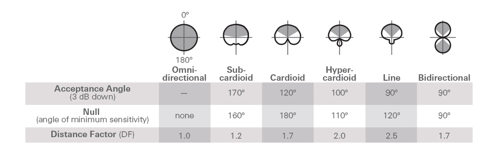
Distance Factor
A directional microphone’s ability to reject much of the sound that arrives from off-axis provides a greater working distance or “distance factor” than an omni. As Fig. 10 shows, the distance factor (DF) for a cardioid is 1.7 while the omni is 1.0. This means that if an omni is used in a uniformly noisy environment to pick up a desired sound that is 10" away, a cardioid used at 17" from the sound source should provide the same results in terms of the ratio of desired signal to ambient noise. Among other microphone types, the subcardioid should do equally well at 12", the hypercardioid at 20" and the bidirectional at 17".
If the unwanted noise is arriving from one direction only, however, and the microphone can be positioned to place the null of the pattern toward the noise, the directional microphones will offer much greater working distances.
Sound Characteristics
From a distance of two feet or so, in an absolutely “dead” room, a good omni and a good cardioid may sound very similar. But put the pair side-by-side in a “live” room (a large church or auditorium, for instance) and you’ll hear an immediate difference. The omni will pick up all of the reverberation and echoes – the sound will be very “live.” The cardioid will also pick up some reverberation, but a great deal less, so its sound will not change as much compared to the “dead” room sound. (This is the “Distance Factor” in action.)
If you are in a very noisy environment, and can point the microphone away from the noise, a comparison will show a better ratio of wanted to unwanted sound with the cardioid than with the omni.
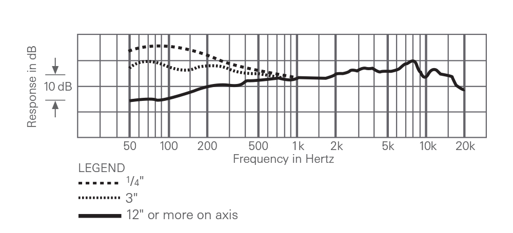
Now, let’s repeat the comparison, but this time with the microphones very close to the source (a singer, perhaps). As you get within about two inches, you’ll notice a rising bass response in most cardioid microphones. This is known as proximity effect (see page 12), a characteristic that is not shared with the omni microphone used for comparison.
Selecting a Polar Pattern
Whether you should select a directional or omnidirectional microphone can depend on the application (recording vs. sound-reinforcement), the acoustic conditions, the working distance required and the kind of sound you wish to achieve. Directional microphones can suppress unwanted noise, reduce the effects of reverberation and increase gain-before-feedback. But in good acoustic surroundings, omnidirectional microphones, properly placed, can preserve the “sound” of the recording location, and are often preferred for their flatness of response and freedom from proximity effect.
Omnidirectional microphones are normally better at resisting wind noise and mechanical or handling noise than directional microphones. Omnis are also less susceptible to “popping” caused by certain explosive consonants in speech, such as “p,” “b” and “t.” Serious recordists will undoubtedly want to have both types of microphones available to be ready for every recording problem.
Line Microphones
When miking must be done from even greater distances, line or “shotgun” microphones are often the best choice. Line microphones are excellent for use in video and film, in order to pick up sound when the microphone must be located outside the frame, that is, out of the viewing angle of the camera.
The line microphone uses an interference tube in front of the element to ensure much greater cancellation of sound arriving from the sides. Audio-Technica line microphones combine a directional (“gradient”) element with the interference tube to increase cancellation at the rear as well.
Figure 11: Line + Gradient Microphone
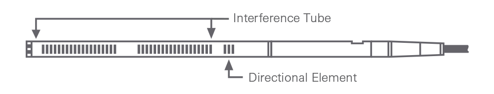
As a general design rule, the interference tube of a line microphone must be lengthened to narrow the acceptance angle and increase the working distance. While shorter line microphones may not provide as great a working distance as their longer counterparts, their wider acceptance angle is preferred for some applications, because aiming does not need to be so precise. (Some A-T shotgun mics employ an exclusive design* that provides the same performance from an interference tube one-third shorter than conventional designs.)
*U.S. Patent No. 4,789,044
Proximity Effect
Proximity effect can either be a blessing or a curse, depending on how it is used. A singer can get a deep, earthy sound by singing very close, then change to a more penetrating sound by singing louder while moving the microphone away. This kind of creative use takes some practice, but is very effective. On the other hand, singing at the same volume (with no special effects desired) and moving the microphone in and out will create problems of tonal balance, apart from changes in overall mic level. Some performers also like to work very close at all times to “beef up” an ordinarily “light” voice.
Proximity effect can be used effectively to cut feedback in a sound reinforcement situation. If the performer works very close to the mic, and doesn’t need the extra bass, an equalizer can be used to turn down that channel’s bass response. This makes the microphone less sensitive to feedback at low frequencies, since it is now less sensitive to any low-frequency signal arriving from more than a foot away. (This equalization technique also will help reduce the effect of any handling noise.)
Feedback
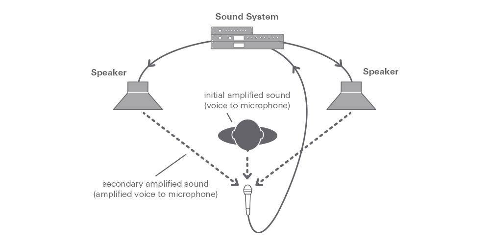
Feedback is simply a condition in a sound-reinforcement application when the sound picked up by the microphone is amplified, radiated by a speaker, then picked up again, only to be re-amplified. Eventually the system starts to ring, and keeps howling until the volume is reduced. Feedback occurs when the sound from the loudspeaker arrives at the microphone as loud or louder than the sound arriving directly from the original sound source (talker, singer, etc.).
The right microphone will reduce the problem. A microphone without peaks in its response is best, as feedback will occur most easily at the frequencies where peaks exist. While a good omni might work well in some situations, a cardioid is almost always preferred where a high potential for feedback exists. When the loudspeaker sound comes primarily from a single direction (rather than mainly reflected from all the walls, ceiling, etc.), the null of a cardioid (or other directional pattern) microphone can be aimed to minimize pickup of the speaker’s sound.
Distance is also a factor. Moving the microphone (or speaker) to lengthen the acoustic path to the loudspeaker can often reduce feedback. Bringing the microphone closer to the desired sound source will also help. And in general, the microphone should always be located behind the speakers.